Equipment Manager - Create/Modify
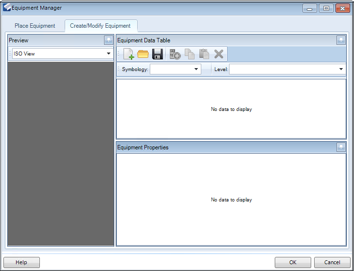
The Create/Modify tab of the Equipment Manager allows you to either create a new equipment component or modify an existing one.
- Parametric from template: You are prompted with a file selection dialog to select an existing equipment component file to use as a template. The equipment component files are saved as .xml files. From the template file, you can make any changes to the properties then perform a Save As to save the component under a new name.
- Cell-based: Create an equipment component from an existing cell which contains the graphical elements for the component. You will be prompted to select the cell library and the specific cell to use. Once this has been defined, you can define properties for the component.
| Setting | Description |
|---|---|
| Preview | This section displays a preview of the equipment component in either the Top, Front or Iso view. You cans select which view to use from the drop down list. |
| New | Click the icon and select which type of Equipment
type to create from the following options:
|
| Open | Click to display an Open dialog, where you can select an existing equipment type template file to load. The equipment component types are saved as XML files. When you click the icon, the Open dialog displays allowing you to navigate to the file location and open it. |
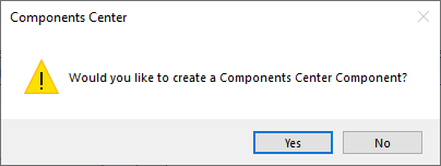
| Save | Prompts you to save the new or modified equipment
component as an XML file in the Save As dialog.
Click Yes to display the Save to Components Center dialog for additional options to define before the component is saved. |
| Add | Adds a new sub-level o the same type as selected under the main Object node. This option is not available when the main (Level 1) object node is selected. |
| Copy | Allows you to copy the selected object which can then be pasted either under the same object node it was copied from, adding another object of the same type, or pasted under a different node if needed. |
| Paste | Pastes the copied object under the selected node. This option is only available if an object was first copied. |
| Delete | Deletes the selected object. You will be prompted to confirm the deletion process. |
| OK | Saves the changes and closes the dialog. |
| Cancel | Closes the dialog without saving the changes. |
 icon to display the
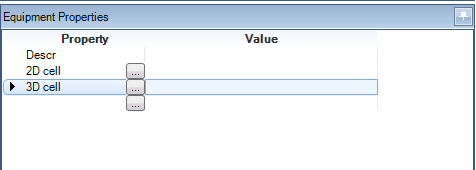
Equipment Properties
| Setting | Description |
|---|---|
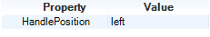
| Object/Level 1 | Level 1 will usually contain some basic component
information such as shown below:
To define/edit the value for a property, either enter a new value directly into the field, or select a value from the drop down list if one is available. To add a new property, click below the last
property and click the Browse
|
| Object/Level 2 | Level 2 properties will usually define the
dimensional parameters of the component:
When defining dimension parameters for an equipment
component, the distance values can be either entered directly into the field,
or you can click the Browse
To add a new property, click below the last property
and click the Browse
|
| Object/Level 3 | Level 3 properties will usually define an attribute
specific to the component:
To add a new property, click below the last property
and click the Browse
|